CAD to Cut
Overview
No matter what end results you would like to achieve , CAD design is the first step of all WAZER operations. Primarily there two major types of CAD procedure when preparing a DXF or SVG: engineering drafting approach and artist drafting approach. This tutorial will focus on the engineering drafting approach from ideation to WAM operation.
In this tutorial you will learn:
How to design your first WAZER cut in SolidWorks and Fushion360
How to import your design into WAM and turn it into a G-Code which the machine can read
The pictures with important fine details can be enlarged by clicking on them.
Select a CAD Program in the drop down.
SolidWorks
Step 1: Creating a Part File
-On the SolidWorks Home Screen, click “File,” then “New,” then select “Part” to create a new part file.
Step 2: Creating a Sketch
-In the top left corner, click the “Sketch” tab on the toolbar and then click “Sketch” to pull up a trimetric display of 3 planes. Select any plane to begin sketching on.
-In the bottom right corner, ensure that the units selected are “MMGS.”
Step 3: Sketching and Dimensioning
-Create a slot entity in the sketch plane by selecting “Straight Slot” in the Sketch Menu.

-Dimension the slot with a 15mm height and 65mm centerline length using the “Smart Dimension” command. Press the “Exit Sketch” button when finished.

Step 4: Extruding a Sketch
-In the toolbar, exit the sketch and click the “Features” tab, then select “Extruded Boss/Base” to extrude the profile you have created.
-Extrude the slot profile 2mm.
Step 5: Creating the Screw Extractor
Create a closed profile in a sketch on top of the extruded geometry by:
1. Starting a sketch on the top surface
2. Drawing a profile with line tools and dimension using “Smart Dimension” with a 6mm wide opening
3. Using parametric relationships like symmetry and other dimensions to fully define your sketch (all lines turn black)
-The profile does not have to match the curve of the edge, it only has to encompass it to cut it away completely.
-Create an extruded cut of the profile by selecting the “Features” tab and selecting “Extruded Cut” and setting the cut direction to “Through All.”
Step 6: Creating the Push-to-Connect (PTC) Tool
Repeat Step 5 and create another profile to create a other side of the tool, except this time, set the fork width to 10mm instead of 6mm.
1. Create a sketch on the top surface
2. Draw profile and dimension with 10mm wide opening
3. Fully define sketch using parametric relationships and dimensions
Extrude away this profile using “Extruded Cut.”


Step 7: Relief Cut
-Create a slot entity sketch profile and extrude cut away. The slot should have 1.5mm width and 9mm length. Take care to ensure the slot is centered up and down in the extruded geometry.
-This cut is made so that the bending of the tool is made easier once cut.

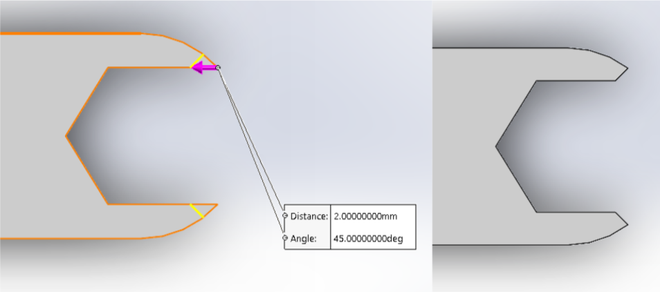
Step 8: Chamfering/Fileting
-Chamfer or filet the sharp tips of the forks so that they are blunted. This is achieved by selecting “Filet” in the “Features” tab and selecting the edges you wish to process.
-Use a 1-2 mm chamfer or filet on the edges.
-Add more filets and chamfers wherever you feel necessary; the smoother the profiles (less corners) the quicker the cuts will be.
Step 9: Importing the WAZER Logo
-Find the WAZER Logo dxf on your computer, and drag the file into SolidWorks
-Place the logo in the center of the tool and extrude cut away the profiles
Step 10: Exporting and Saving as DXF
-Click the large flat face of the tool and press “Ctrl+8” keys at the same time to view the part normal to that plane.
-Save the part as a SolidWorks Part file, and also as a DXF file.
-When saving as a DXF, the menu depicted should pop-up, select “Current” under “Views To Export.” Make sure the DXF cleanup window that comes up, as pictured on the left, looks clean with no extraneous geometry.
Once you’re done with your CAD Drawing, continue to the “Wam Operation” steps to learn how to turn your DXF File into G-Code.
Fusion 360
Step 1: Creating a Part File
-Fusion automatically opens up an empty new file each time it is booted up. Once booted, you are ready to start designing your first WAZER Cut.

Step 2: Creating a Sketch
-In the top left corner, click the “Create Sketch” tab on the toolbar to pull up a trimetric display of 3 planes. Select any plane to begin sketching on.
Step 3: Sketching and Dimensioning
-Create a slot entity in the sketch plane by selecting “Center Point Slot” in the “Create” dropdown menu in the top left.
-Dimension the slot with a 15mm height and 65mm centerline length using the “Dimension” command which can be engaged by pressing “D” on the keyboard. Press the “Finish Sketch” button when finished.
Step 4: Extruding a Sketch
In the toolbar, click the green “Finish Sketch” checkmark button, then select “Extrude” to extrude the profile you have created.
-Extrude the slot profile 2mm
Step 5: Creating the Screw Extractor
Create a closed profile in a sketch on top of the extruded geometry by:
1. Starting a sketch on the top surface
2. Drawing a profile with line tools and dimension using “Dimension” with a 6mm wide opening
3. Using parametric relationships like coincidence and other dimensions to fully define your sketch (all lines turn black)
-Click “Finish Sketch” and then “Extrude.” Click the profile that will be cut away. Select “Symmetric” in the direction selection and “All” in the Extent type selection. Ensure that the operation says “Cut.”
Step 6: Creating the Push-to-Connect (PTC) Tool
Repeat Step 5 and create another profile to create a other side of the tool, except this time, set the fork width to 10mm instead of 6mm.
1. Create a sketch on the top surface
2. Draw profile and dimension with 10mm wide opening
3. Fully define sketch using parametric relationships and dimensions

-Extrude away this profile using “Extrude” with settings “Symmetric” Direction and “All” as Cut Extent.

Step 7: Relief Cut
-Create a slot sketch profile and extrude away. The slot should have the 1.2mm width and be centered 3.3mm from each edge.

-This cut is made so that the bending of the tool is made easier once cut.

Step 8: Chamfering/Fileting
-Chamfer or filet the sharp tips of the forks so that they are blunted. This is achieved by selecting “Chamfer” in the “Modify” drop down menu and selecting the edges you wish to process.
-Use a 1-2 mm chamfer or filet on the edges.
-Add more filets and chamfers wherever you feel necessary.
Step 9: Importing the WAZER Logo
-Find the WAZER Logo on your computer, and drag the file into Fusion 360 or click the “Insert” drop down menu in the top toolbar and select “Insert DXF.” Click the top plane and select the logo file and click “OK.”
-Drag the logo into the center of the tool and extrude cut away the profiles.
Step 10: Exporting and Saving as DXF
Fusion 360’s built in DXF Exporter does not work every time; the work around is as follows:
1. Click the surface of interest
2. Create a new sketch on the surface and finish the sketch without drawing any new lines
3. Go to the Folder Tree in the top left corner and in the “Sketches” folder, right click the new sketch
4. Select “Save as DXF” in the right click menu
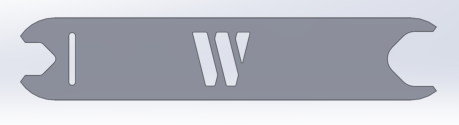
-This is what your final DXF should look like.
Once you’re done with your CAD Drawing, continue to the “Wam Operation” steps to learn how to turn your DXF File into G-Code.
Wam Operation
If you ever find yourself stuck on a step in Wam, there is a “?” button in the bottom right corner of each drop down menu of each step detailing how each step should be executed and what they do.
Step 11: Importing File into Wam
-Open up WAM in your browser: wam.wazer.com
-Import the newly created DXF and drag it to the center of the cut bed by clicking “Import File” (this position can be changed later on the physical machine itself).
-Use the scroll wheel to zoom in and out on the cut bed
Step 12: Scale and Position Cut
-Click “Scale and Position” next. In this case, since our geometry is true to size, scaling is not necessary. Make sure the “Scale” parameter is set to 1.000 or else the tool will not be appropriately sized
-In other cases scaling is done by clicking the geometry and adjusting the “Rotation” and “Scale” parameters as desired
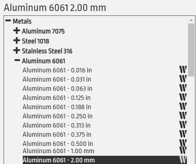
Step 13: Material Selection
-Click “Material.”
-Select the appropriate material to be cut from the drop-down menus.
-In this case, we will be using 2mm thick Aluminum 6061, make sure the geometry is selected.
-Select the options seen in the picture on the above.
-The material is selected once highlighted in black.
Step 14: Cutting Path
-Click “Cutting Path”
-The green line denotes the cutting path.
-Make sure that the geometry is selected, then select “Outside.”
Step 15: Tabs and Leads
-Click “Tabs and Leads”
-Tabs hold cut away material to the original piece of material, ensuring that loose pieces do not fly away and get stuck under the nozzle, creating problems during cutting.

-Yellow marks denote tabs.
-On long, skinny pieces, the ideal tab placement would be in the middle of the piece to lower chances of the tab breaking during cutting.
-Tabs can be dragged to the desired location.
-The blue line denotes the lead-in that the tool will take to improve cut quality.
The Final Step
- Select the desired cut quality, double check the cut time and abrasive usage
- Rename the file name
- check the “Download“ button, and you will get the cut file (g code) downloaded to your computer.