Cut Project General Work Flow
Overview
This article will give you a high level view of how the typical cut project is carried out, from conceptualization, to the final cut execution. At the start of this article, a few formalized terms will be listed out in chronological order. Then at each step, a brief explanation and a few pointers will be provided.
Formalized Terms
Cut Project: The whole process from design, compute, execute, to finish
Cut Profile: Lines and dots that constitute a shape that user envisions. It can be in all file types.
Design File: Files that user originally designed in
Exported File: File that was exported from the design file, ready to be imported into WAM. This exported design files is readily called an SVG or DXF.
Cut File: WAM generated G code that is ready to be transported into SD card. This term is interchangeable with "G code"
Cut Result: The end result of the cutting on pre-determined material.
General Workflow
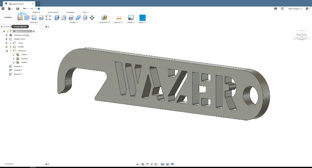
To start a cut project, we first need to design or create a cut profile in the computer. Using a CAD program, such as SolidWorks, or a design software like Inkscape, Adobe Illustrator, etc., is the best and quickest way to create a custom profile. The custom profile can be in either 2D or 3D. With that being said, WAZER can only cut 2D shapes, so if you designed the profile in 3D, you may need to convert the 3D object in 2D planar profile before moving on. So, keep that in mind.
Typically, we refer to these created profiles as the “design file” of your project. The design file can be in all kinds of format, such as .sldprt for Solidworks, .ai for Illustrator. Once we have finished designing our design files in CAD, we export it. For our WAM software to recognize the design files, it will need to be exported as DXF, or SVG. If you are having trouble getting WAM to import your exported file, it might indicate a version compatibility issue. If so, please refer to this page for DXF generation and this page for SVG generation. Please keep in mind that DXF is a more engineering or technical oriented file type (3D), while SVG can be mostly seen as a drawing in a 2D space.

After we have our design files exported as one of the above file types, we can upload the file into WAM. Navigating through WAM, we can customize our cut profile in a few different ways. You can see all the options on the left side of the screen. Deciding scale, position, material, cutting path, and tabs/leads are all very vital in order to get our cut profiles to come to life. All changes will be live viewed on the virtual cut bed on the right side of the screen. After setting up our cut profile exactly how we want it cut in WAM, we export the newly edited file, as a cut file (file type is gcode). This is the file you will be uploading to the SD Card. WAZER is only capable of reading gcode that has been generated inside of WAM.

Before transferring that G code file to the SD Card and starting the cut, we always recommend visualizing that G code to check for anything out of place. Visualizing G code can give us a large amount of feedback on exactly how the WAZER will cut our blueprint. In order to save the material you are cutting from any design flaws that you may overlook in previous steps, https://ncviewer.com will become a very useful tool. Visualizing G code should be done often, if not, then all the time. If uncertain on how to visualize G code, please follow the guide here.

If we are satisfied with the gcode we have produced in WAM, and the g code visualization matches what we envisioned with our ultimate cut result, it’s time to bring our cut profile to life.
The last step is to transfer the generated cut file (G code) onto the SD card and prepare your WAZER for cutting!