Dry Abrasive Priming
The Dry Abrasive Subsystem is a vital system to the WAZER Water Jet! The flow-rate must be metered at all times of operation. In order to help maintain the ideal flow-rate before your first cut, a wedge has been installed into the dry abrasive drop tube. This wedge will need to be removed before initiation and is not necessary after a few hours of run time.
Required Tools:
None
Parts Needed:
Wedge on string
Tupperware/Cup
Weight measuring scale capable of measuring grams
Procedure:
Pull the left side abrasive drawer open.
2. Remove the instructions bag from the top of the drawer. It contains the following parts:
Abrasive Drop Tube - The abrasive drop tube can be kept as a spare and used for replacement if an issue occurs. See the drop down below for abrasive drop tube replacement instructions. In the meantime, please keep this spare somewhere safe.
Priming Instructions - The condensed version of the priming procedure. This article will review the steps in more detail!
3. Remove the tape from the abrasive mesh screens and set the screens off to the side.
4. Do not remove the wedge at this time. Before doing so, press the abrasive pinch valve button manually and keep it held in.
5. While holding the pinch valve button, pull the wedge straight upwards. The wedge can be held onto for future use if there will be extended down time. However, it is not needed after the first few hours of operation.
6. Double check to make sure the abrasive orifice is seated into the drop tube correctly. It should catch the top of the drop tube and is pushed firmly into the bottom of the hopper.
7. With the wedge removed and the abrasive orifice seated correctly, the dry abrasive system is ready to run! As a final verification, the flow-rate can be measured. To do so, a small cup and scale is needed. Make sure to tare the weight of the cup out of the scale. Remove the abrasive catcher and hose from the pinch valve. Place the cup below the pinch valve.
8. Reinstall the abrasive mesh filters on top of the hopper. Pour enough abrasive through the top filters until the hopper is about ¼ full.
9. Run the “Abrasive Flow-rate” test under the Maintenance menu. This will run the hopper assembly for 60 seconds. Afterwards, measure the abrasive captured in the bowl. The ideal flow-rate is 140g/min +/- 10g/min.
10. If the flow-rate is out of spec, there are replacement abrasive orifices located in the black tool kit. They are labeled:
H - Increases flow rate by ~10g/min
L - Decreases flow rate by ~10g/min
11. Swap the necessary orifice with the original and re-test the flow-rate. If the flow-rate is inconsistent or is still not within the acceptable range, the rubber drop tube may need to be replaced. Please reach out to the WAZER Support Team at support@wazer.com for further assistance.
Abrasive Drop Tube Replacement
Required Tools:
2mm hex key
2.5mm hex key
Philips screwdriver
Disconnect Vibration motor leads and abrasive hose.
2. The Abrasive Hopper needs to be removed from WAZER.
3. Remove the Abrasive slip cover.
4. The abrasive tank will need to be emptied of abrasive. Dump all abrasive out of Abrasive Hopper.
5. Remove Abrasive Orifice from inside the abrasive hopper, by simply pulling up on it and then set it aside.
6. Remove the 4x M3 screw securing the pinch valve to its bracket.
7. Depress pinch valve button and pull the tube out.
8. Remove the valve from the hopper. Inspect for any damage.
9. Disconnect the electric plug and verify the contacts are clean.
10. Unscrew the four 2.5mm screws from the valve head.
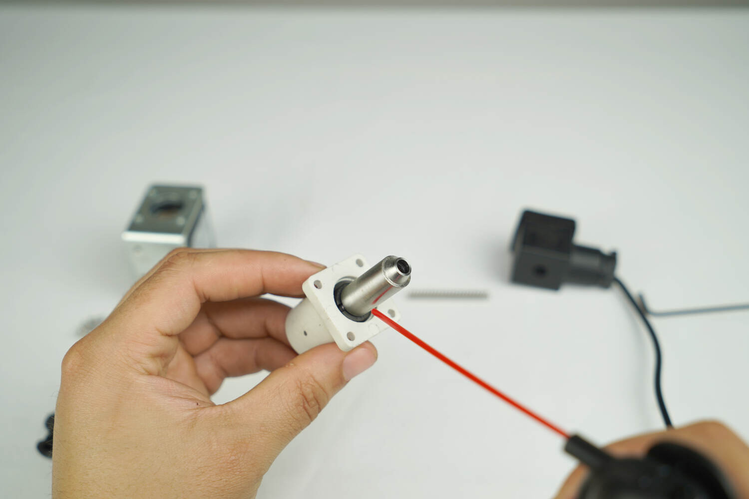
11. Pull off the valve head along with brass bushing.

12. Remove the brass bushing from the valve head shaft.

13. Remove the spring.

14. Press the button and remove the drop tube.

15. Use compressed air to thoroughly clean the whole valve head and solenoid body.
16. Thoroughly clean the brass bushing.
17. Reinstall the spring.
18. Reinstall the brass bushing onto the shaft and make sure it's fully seated.
19. Make sure none of the parts are missing. Insert the steel rod part of the white body of the pinch valve into the solenoid body. Note orientation, white body slot is aligned to the valve label. Wiggle a bit to center
20. Press the black button and insert the drop tube. Make sure to note the orientation.
21. Replace the 4x M3 bolts with a 2.5mm hex wrench.
22. Reattach the electrical connection.
23. Push drop tube through hopper and seat the pinch valve. Reattach the valve to the hopper bracket with the M3 2mm screws.
24. Pull tube through until the end sits flush on the other end of the white pinch valve head. Look through the tube to confirm there are no bends. We recommend shining a light through one end and looking from the other.
25. Install Abrasive Orifice.
Push up slightly on the abrasive valve assembly to make installation easier.
When the metal orifice is in the tube, push it down until fully seated in bottom of the tank.
Make sure the lip of the drop tube is sandwiched between the hopper bottom and abrasive orifice.
26. Re-install Abrasive Slip Cover, reconnect the vibration motor leads, and Abrasive Hose.
27. Re- install Abrasive Hopper into WAZER.